-01.png?width=926&height=181&name=Netgate%20Logo%20PMS%20(horizontal)-01.png "Netgate Main Logo")
%201.png?width=302&name=Netgate%20Logo%20PMS%20(horizontal)%201.png "NetgateColorLogoRegisteredRGB.png")
TGW Primer
A Transit Gateway (TGW) is an AWS Cloud-Native regional network transit hub that can interconnect up to 500 attached VPCs.
VPCs can connect to the TGW using VPC attachments. Each VPC attachment is a virtual link that allows traffic to flow between the VPC and the Transit Gateway. When a VPC attaches to a TGW, a subnet will be specified for each availability zone, and TGW will create an interface in that subnet. When created, TGWs will have a default route table, and all attachments will be associated and propagated to the default route table.
Customers can create multiple route tables in the TGW for network isolation. VPC attachments are associated with a route table and can propagate to one or more TGW route tables to control routing. In this discussion, we will use the single default route table.
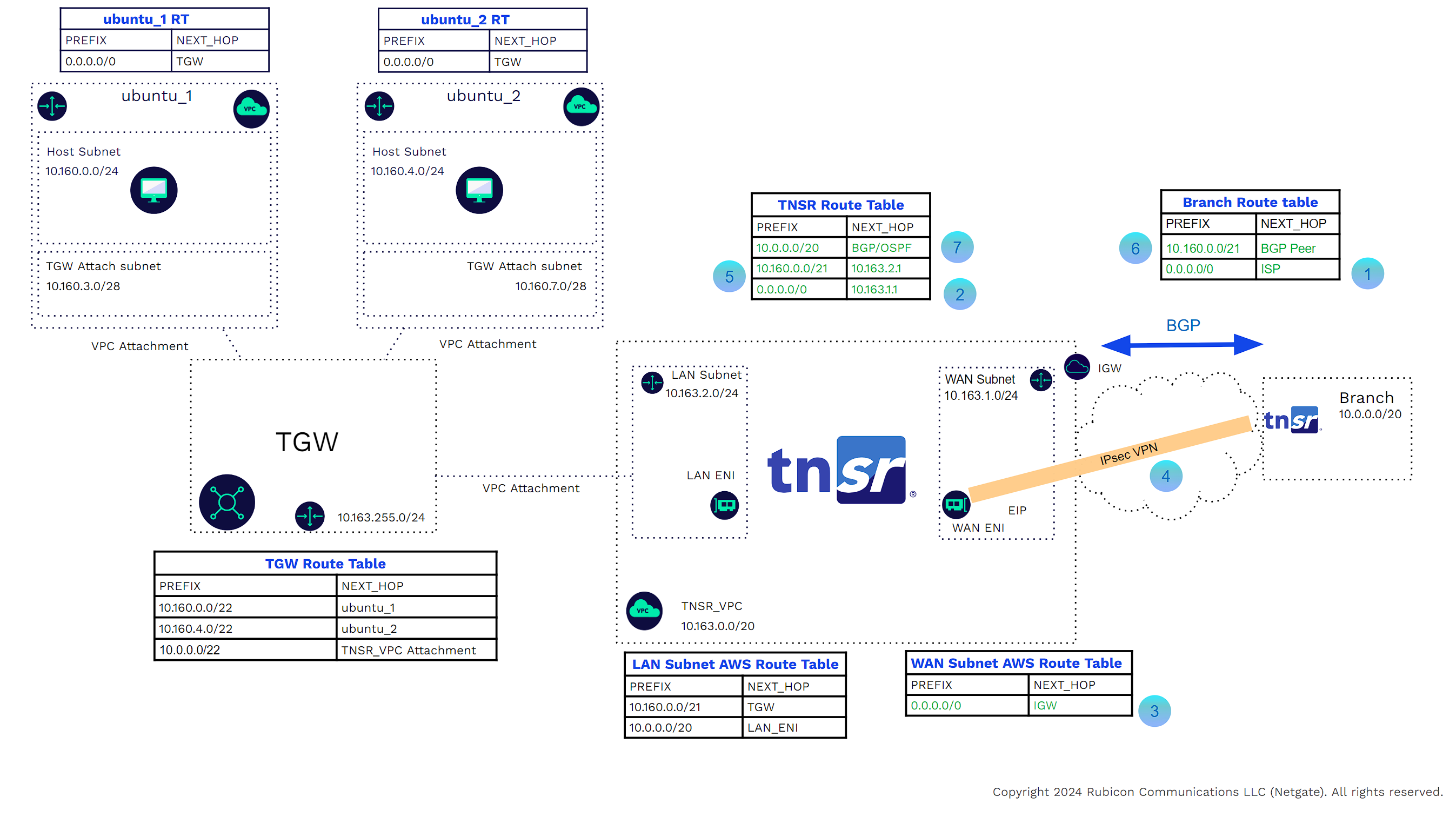
In the example below
![]()
A host in VPC ubuntu_1 needs to communicate with a host in VPC ubuntu_2. Traffic leaving the source host will use the VPC main or subnet-specific route table where the default route points to the TGW as the next hop.
![]()
The host in VPC ubuntu_1 will use the virtual link to send the traffic to the TGW.
![]()
The TGW, having received traffic from the ubuntu_1 VPC attachment, will look at its route table. The TGW route table shows that the next hop for 10.160.4.0/22 is VPC attachment ubuntu_2.
![]()
The TGW will use the virtual link to send the traffic to VPC ubuntu_2.
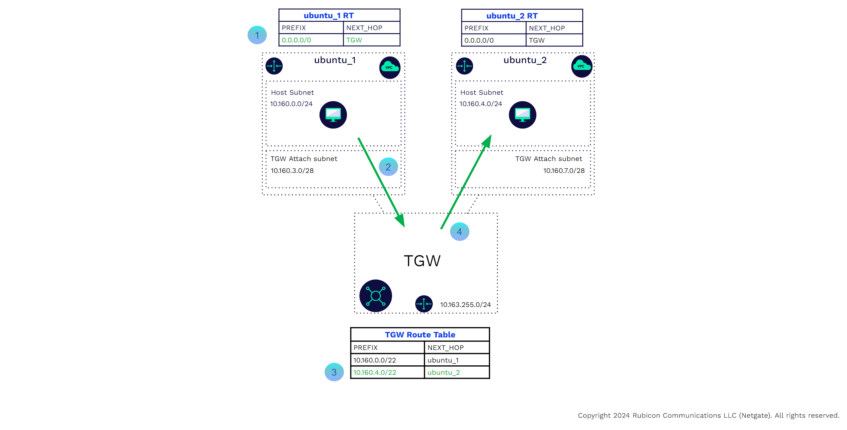
Return traffic from the host in ubuntu_ 2 to ubuntu_1 will perform similar steps.
Transit Gateways also provide external connectivity to data centers, branches, and remote clients using Direct Connect Gateway and VPN Attachments. These external connections take advantage of Dynamic Routing and ECMP.
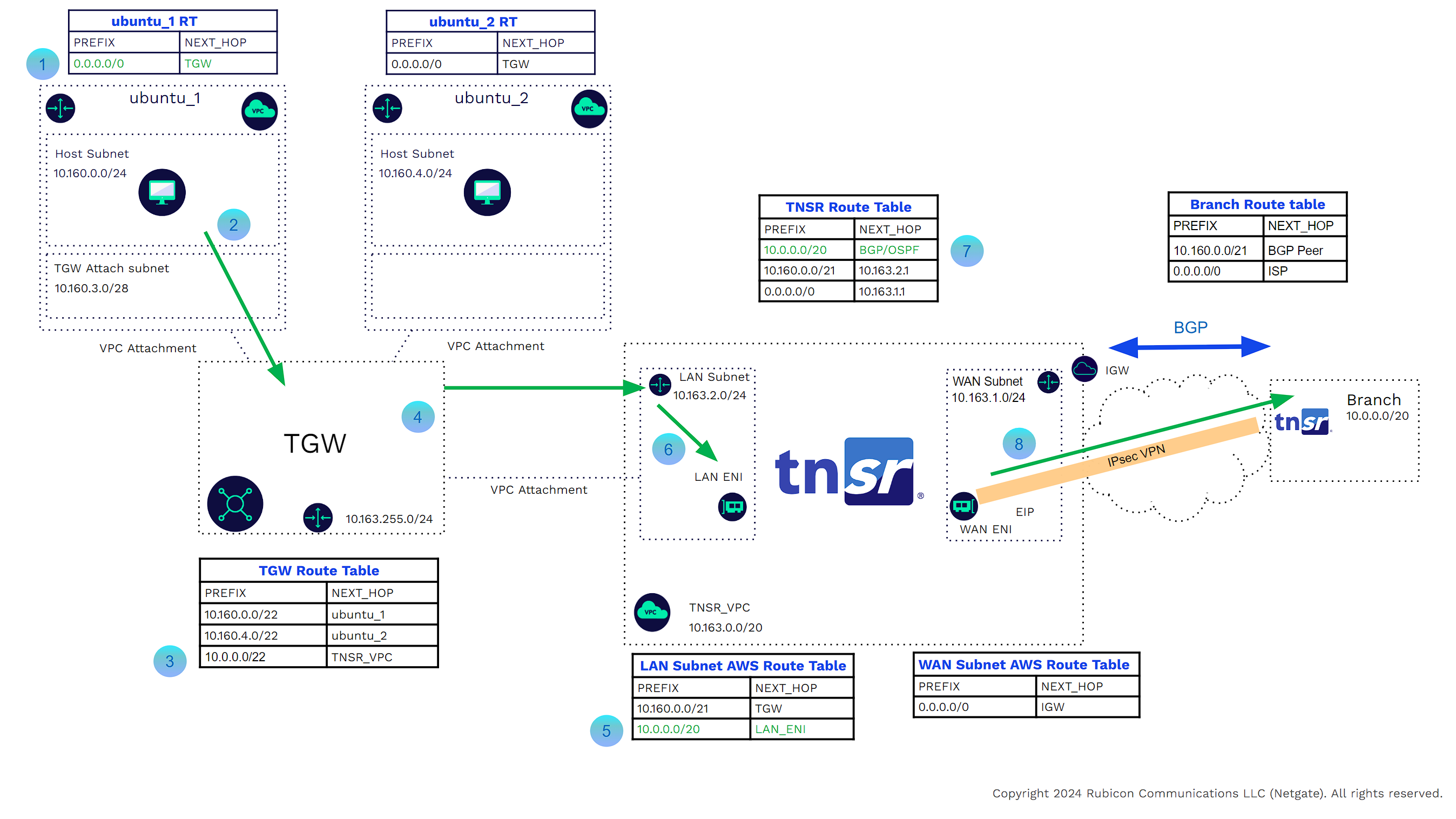
In the example below
![]()
A host in VPC ubuntu_1 needs to communicate with an external enterprise host. Traffic leaving the source host will use the VPC main or subnet-specific route table, where the default route points to the TGW as the next hop.
![]()
The host in VPC ubuntu_1 will use the virtual link to send the traffic to the TGW.
![]()
The TGW having received traffic from the ubuntu_1 VPC attachment will look at its route table. The TGW route table shows that the next hop for 10.0.0.0/20 is VPN Connection 1. This was learned from BGP.
![]()
The TGW will send the traffic to the branch through the site-to-site VPN connection.
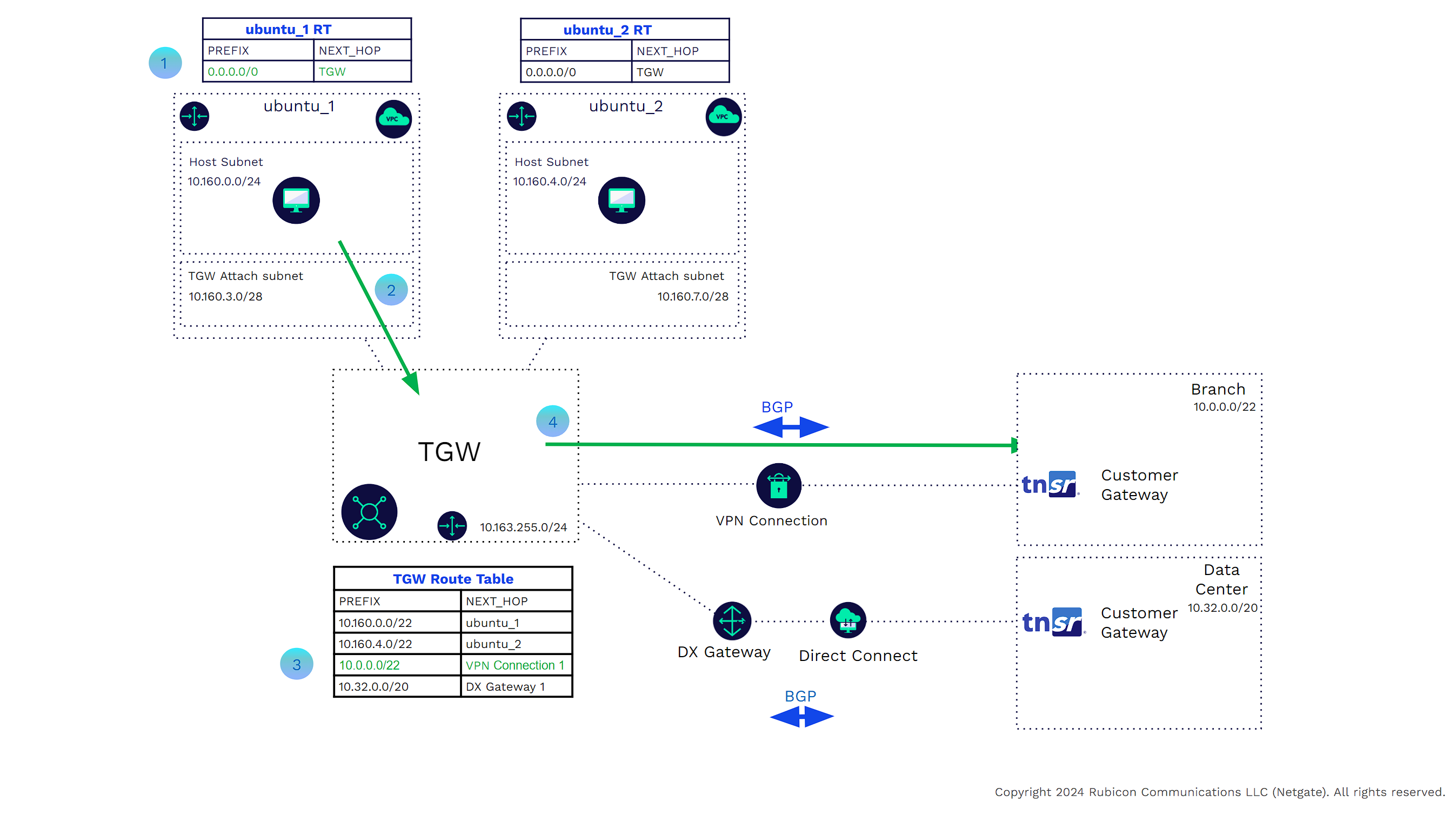
The branch to VPC traffic is reversed.
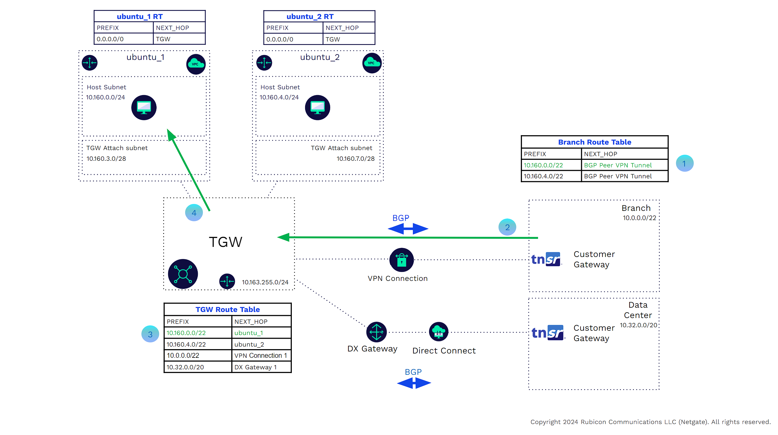
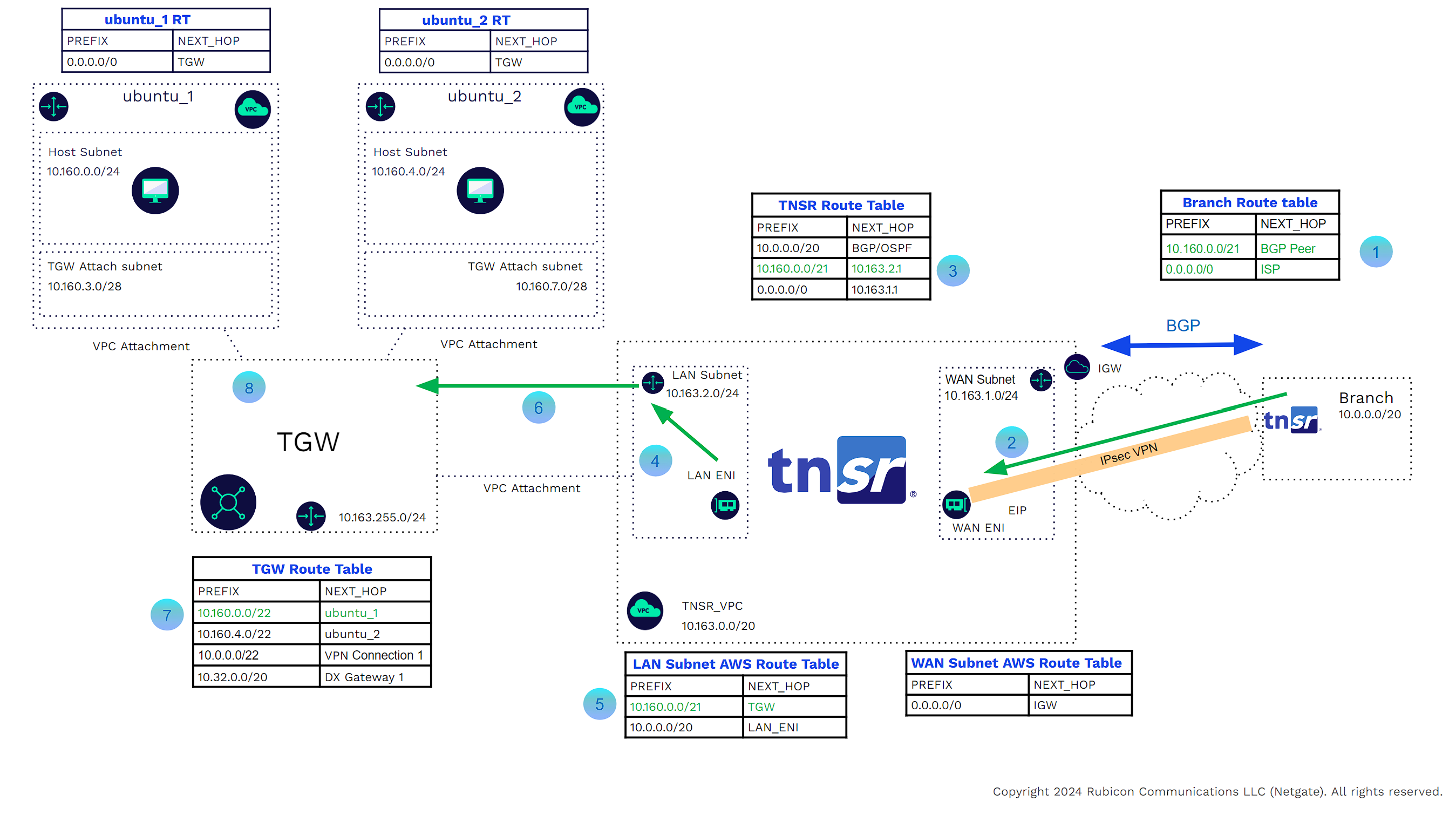
In the example below
![]()
A host in branch 1 must communicate with a host in VPC ubuntu_1. The branch router learns via BGP that the next hop is the other side of the VPN tunnel.
![]()
The branch router sends the traffic through the VPN tunnel.
![]()
The TGW, having received traffic from the ubuntu_1 VPC attachment, will look at its route table. The TGW route table shows that the next hop for 10.160.0.0/20 is VPC attachment ubuntu_1.
![]()
The TGW will use the virtual Link to send the traffic to VPC ubuntu_1.
Customers may prefer the TNSR VPN Concentrator instead of the AWS VPN offering. There are several reasons for this.
Performance
AWS VPN tunnels are limited to 1.25 Gbps of throughput. While ECMP may be used to create multiple tunnels, this gets complicated and there is no guarantee of equal distribution (depends on 5 tuple hash). As mentioned, TNSR software's performance scales based on the underlying hardware and network. Right-sizing CPU and memory allows the software to achieve higher performance.
Features
TNSR software offers the full open BGP standard. Customers can use all standard BGP attributes to control traffic flows between their locations and the AWS edge. Customers may leverage route filtering, community strings, route maps, etc. The VPN connection may be IPsec or WireGuard®. Customers may also use OSPF between the branch and AWS TNSR Edge.
Manageability
TNSR software can export data to Prometheus, ERSPAN and IPFIX, allowing customers to use their existing on-site monitoring solutions. Using the same configuration commands across platforms helps streamline operations.
Cost
TNSR software cost scales based on how many tunnels will be terminated. For example, when configuring a VPN in AWS Pricing Calculator, 25 VPN terminations (four site to site, and 21 clients, 24 hours a day) would be $1194/mo. TNSR 25 in AWS Marketplace is $2365/year + EC2 costs(m6i.large) of ~$840. This pricing reflects an annual discount for TNSR software and no savings plan selected for AWS EC2 charges. TNSR software pays for itself in a little over 4 months. This doesn’t take into account the potential cost savings of using TNSR software as a NAT Gateway, which can be an attractive alternative to other NAT Gateway options.
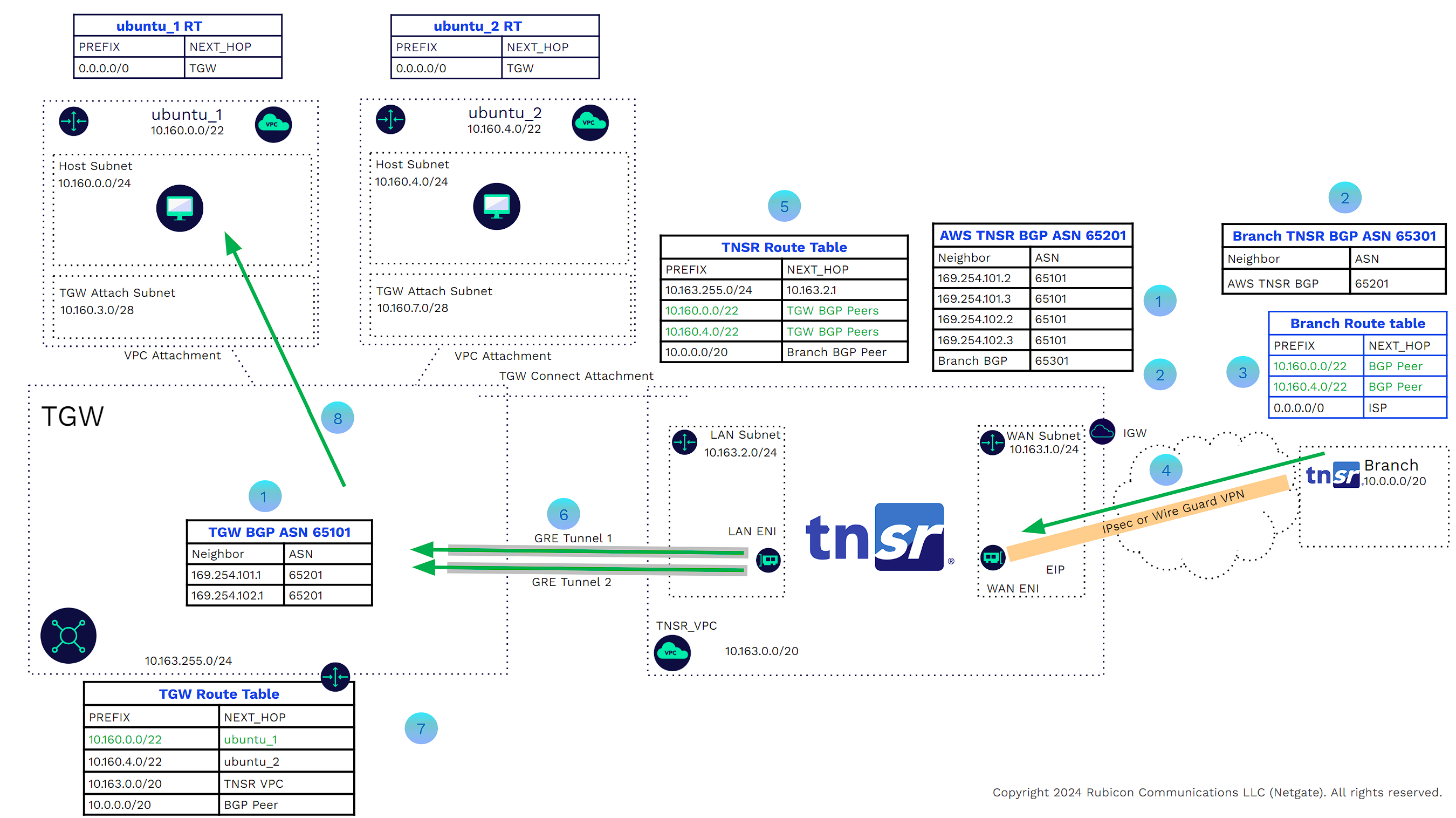
TNSR TGW Attachments
Customers can deploy a TNSR VPN Concentrator in a VPC and attach that VPC to the TGW. Here is an example of the routing required to connect a branch to a TNSR router. The branch router can be a TNSR Bare Metal Image (BMI), a TNSR Virtual Machine, a TNSR Netgate Appliance, or any router (Cisco, Arista, Juniper, etc.)
The cloud TNSR VPN concentrator will have three Interfaces. LAN, WAN, and Management. Each interface will be in a separate subnet with its own routing table. The management interface will not be part of the data plane. The management interface should be protected and preferably only available through a bastion VPC or host. That subnet will be removed from subsequent images as it is irrelevant to the example.
In the examples, it is assumed that the IPsec and/or WireGuard, and BGP/OSPF configurations have been done on both sides. IPsec and BGP are assumed for the rest of these examples.
In the example below
![]()
The branch router has a default route to ISP and can reach the TNSR WAN interface EIP.
![]()
The TNSR router has a route to the branch public tunnel interface with the next hop being the AWS WAN subnet router (in our example we use a default route).
![]()
The AWS WAN subnet router has a route to the branch public tunnel interface with the next hop being the AWS internet gateway for that VPC.
![]()
The VPN tunnel will form and BGP peering will be established.
![]()
Any BGP routes (Learned, redistributed, or network statements)in the TNSR table (assuming no route filtering).
![]()
Will be seen by the branch router.
![]()
Likewise, the TGW will see the branch routes.
The challenge is that there is no BGP Dynamic routing between the TGW and any 3rd party instance inside an attached VPC.
- Engineers must create one or more static routes in the TGW route table for the external enterprise IP address ranges. The next hop for these addresses will be the Attached VPCs that contain the virtual appliance.
- Engineers will also need to add one or more static routes in the LAN subnet route tables for those external addresses. The next hop for these addresses will be the LAN interface of the TNSR virtual appliance.
- The TNSR appliance will also need static routes for the workload VPC addresses. The next hop would be the LAN subnet router. These routes also need to be redistributed into BGP.
In the example below, a host in the branch needs to access a host in AWS VPC ubuntu_1
![]()
The branch router has the route to AWS ubuntu_1 VPCs CIDR Address Range with the next hop being TNSR on the other side of the VPN tunnel.
![]()
The branch router will send the packets through the VPN tunnel.
![]()
The TNSR route table has a static route for the VPC address ranges with the next hop being the LAN subnet AWS router.
![]()
TNSR sends the packet out the LAN Interface to the LAN subnet AWS router.
![]()
The LAN subnet AWS router has a static route for the VPC address ranges with the next hop being the TGW.
![]()
The packet will be forwarded to the TGW using the VPC attachment virtual link.
![]()
The TGW has a propagated route for the ubuntu_1 VPC addresses.
![]()
The TGW will use the VPC attachment virtual link to send the packets to the ubuntu_1 VPC
In the example below, a host in ubuntu_1 VPC needs to connect to a host in the branch
![]()
The ubuntu_1 Host Subnet AWS router has the Next hop for all traffic as being the TGW.
![]()
The traffic is sent across the VPC attachment private link to the TGW.
![]()
The TGW route table has a static route for the branch Address CIDR Range with the next hop being the TNSR_VPC VPC Attachment.
![]()
The TGW uses the VPC attachment private link to send the packets to the LAN subnet of the TNSR_VPC.
![]()
The LAN subnet AWS router sees a static route for the branch Address CIDR range with the next hop being the TNSR LAN Interface.
![]()
The packets are forwarded to the TNSR LAN interface.
![]()
The TNSR Route Table has a BGP route for the branch address CIDR range with the next hop being the other side of the VPN tunnel.
![]()
Packets will be forwarded through the IPsec or WireGuard VPN tunnel to the branch.
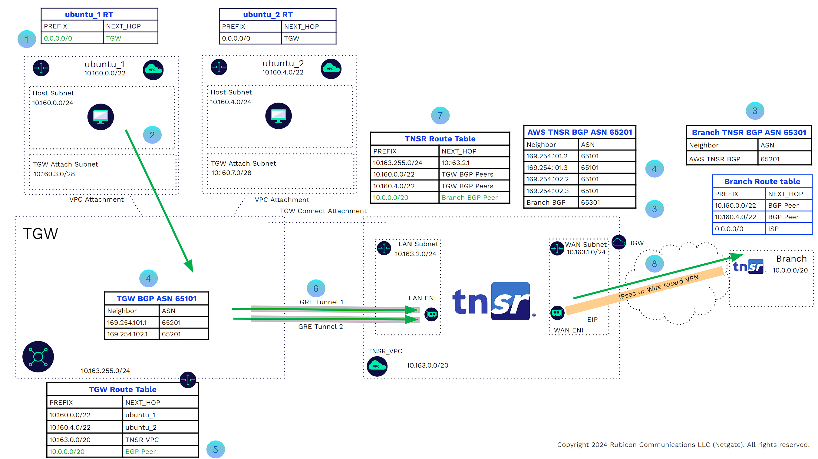
TNSR TGW Connect
As the routing between the TNSR instance and TGW is static, should an instance of TNSR software fail, the AWS LAN subnet route table would blackhole traffic. While it can instantiate another TNSR VPN concentrator in another AWS Availability Zone, the TGW has no way of knowing a device is down and will continue to send traffic to the failed appliance. Any failover would need to be manual.
Another challenge is that static route entries will need to be manually added for the external and VPC CIDRs (good route summarization may alleviate this challenge).
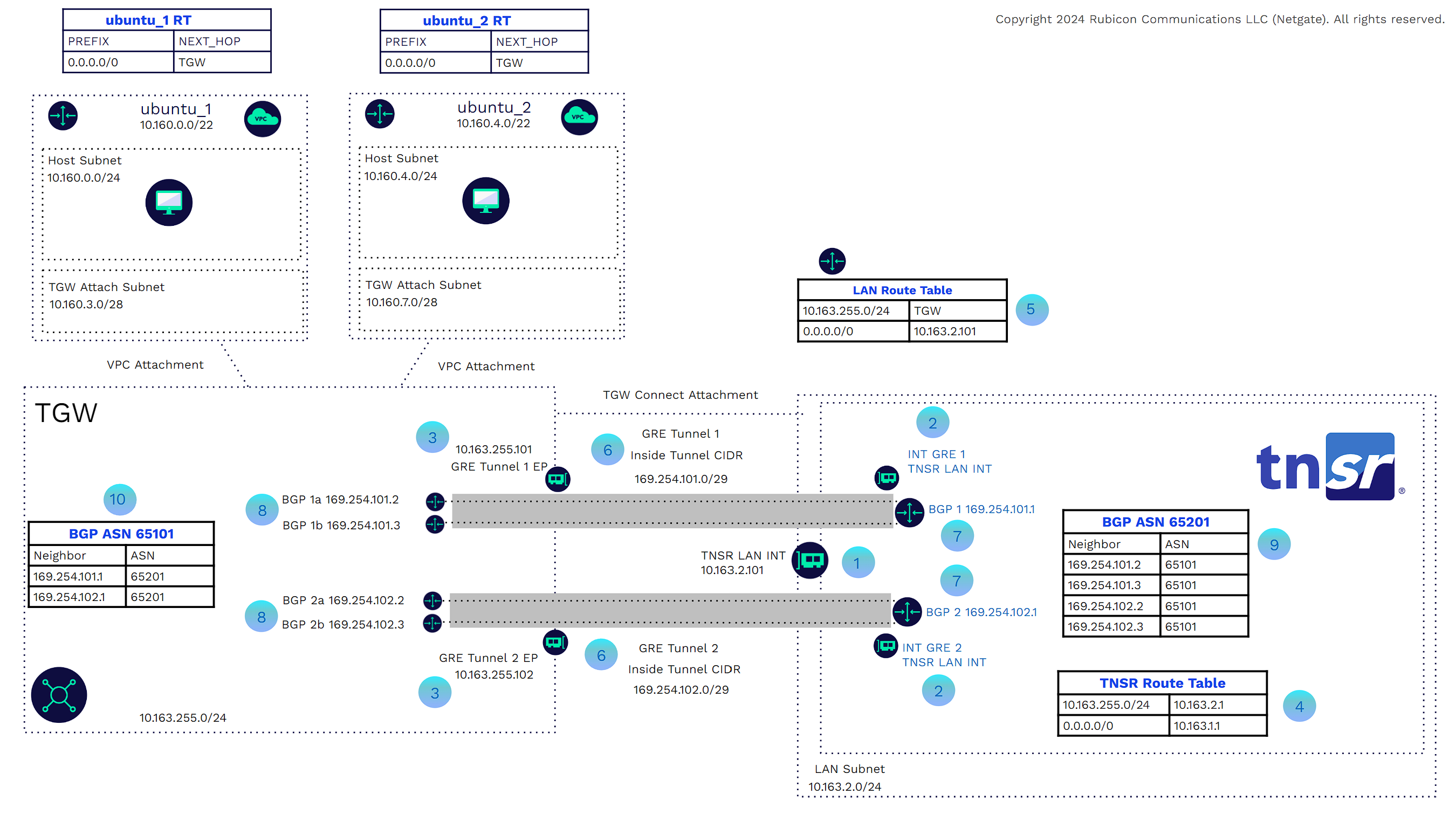
TNSR VPN concentrator deployed with TGW Connect solves these challenges. The TGW Connect solution provides the virtual link between the VPC and TGW, but also allows BGP dynamic routing between the TNSR VPN concentrators and the TGW. The BGP Peering relationships are formed through a pair of GRE encapsulated tunnels that form through that virtual link. The TGW provides two BGP endpoints for each GRE tunnel, providing additional redundancy. Let’s take a closer look at the components of the solution. In the example below, we will only look at how the GRE tunnels and BGP peering between the TNSR and TGW. In later examples, we will show the complete flow from branch to VPC and vice versa.
![]()
The TNSR VPN Concentrator LAN interface is one of three server ENIs. The LAN Interface will be the TNSR GRE tunnel source.
![]()
These are the TNSR GRE virtual interfaces. The source is the TNSR VPN concentrator LAN interface.
![]()
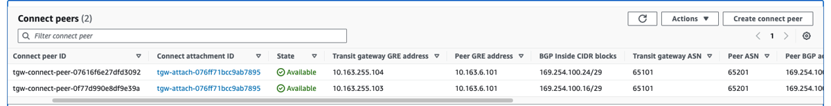
These are the GRE endpoints on the TGW side. TGW will assign these from the TGW address range or we can manually assign these during configuration. Manually assigning these addresses allows for consistency.
![]()
This is the TNSR route table that will be populated through BGP. We do have a static route for the TGW IP address range pointing to the AWS LAN subnet route table. This is because we need to get to the TGW GRE IP addresses to form the tunnel.
![]()
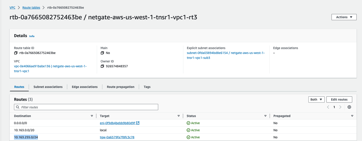
This is the AWS LAN subnet route table. It has a route pointing to the TGW for the TGW IP address range. That allows for the GRE tunnel termination.
![]()
We can now create the GRE tunnels. These are formed using IP addresses of the GRE Interfaces of the TNSR and the GRE Endpoints of the TGW. The tunnel inside CIDR must come from the 169.254.0.0/16 address range with a /29 Netmask. Each GRE tunnel has a maximum bandwidth of 10 Gbps.
![]()
These are the BGP peers on the TNSR side. The IP addresses must come from the GRE tunnel inside CIDRs, and be the first IP addresses in those ranges. (In AWS, subnets we do not count the first three IP Addresses in a CIDR Range. This is not the case here. We use the first IP Address.)
![]()
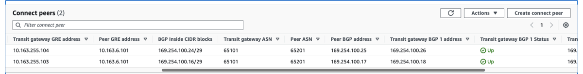
These are the BGP peers on the TGW side. The IP addresses must come from the GRE tunnel inside CIDRs, and be the second and third IP Addresses in those ranges. (In AWS, subnets we do not count the first three IP Addresses in a CIDR Range. This is not the case here. We use the second and third IP addresses.)
![]()
This is the TNSR BGP ASN Process with BGP neighbor configurations pointing to the TGW BGP Peers.
![]()
This is the TGW BGP ASN process with BGP neighbor configurations pointing to the TNSR BGP peers.
In the example below, we can look at the traffic flow from the branch to VPC.
![]()
The TGW BGP router and AWS TNSR router are peered.
![]()
The AWS TNSR router and the branch TNSR router are BGP peered through the VPN tunnel.
![]()
The branch TNSR route table shows a BGP route for the AWS ubuntu_1 with the next hop being the AWS TNSR peer.
![]()
The branch TNSR sends the packets through the VPN tunnel to the AWS TNSR.
![]()
The AWS TNSR route table has a route for the ubuntu_1 prefix with the next hop being the TGW BGP peers.
![]()
TNSR will send the packets through the GRE tunnels to the TGW.
![]()
The TGW route table has a route for the ubuntu_1 prefix with the next hop being the attached ubuntu_1 VPC.
![]()
The TGW will use the virtual link to send the traffic to ubuntu_1.
In the example below we can see the VPC to branch traffic
![]()
The ubuntu_1 Host subnet AWS router has the next hop for all traffic as being the TGW.
![]()
The traffic is sent across the VPC attachment private link to the TGW.
![]()
The AWS TNSR router and the branch TNSR router are BGP peered through the VPN tunnel.
![]()
The TGW BGP router and AWS TNSR router are peered.
![]()
The TGW route table has a BGP route for the branch CIDR with the next hop being the BGP peers on the TNSR VPN router.
![]()
TGW will send the packets through the GRE tunnels to the TNSR instance.
![]()
The AWS TNSR route table has a route for the branch prefix with the next hop being the VPN tunnel.
![]()
Packets will be forwarded through the IPsec or WireGuard VPN tunnel to the branch.
There is now full dynamic connectivity between external sites up to the AWS workload VPCs (5000 per TGW). As branch sites connect to the VPN concentrator, TNSR will advertise the CIDR ranges to the TGW. When new VPCs are attached to the TGW, those CIDR ranges will be advertised to the branches. Traffic engineering may be used, such as route summarization, distribute lists, prefix lists, etc.., to granularly control route distribution.
High Availability
Availability and redundancy may be increased by instantiating a TNSR VPN concentrator in another Availability Zone within the same VPC, or a separate attached VPC. The transit gateway can use ECMP between connected peers in the same VPC or a separate VPC. The default hold time and hold timer are 10 and 30 seconds. Should the TGW lose BGP connectivity (active state) with a TNSR instance, TGW will remove that instance as a next hop; however, the TNSR instance in the different availability zone will still advertise those routes.
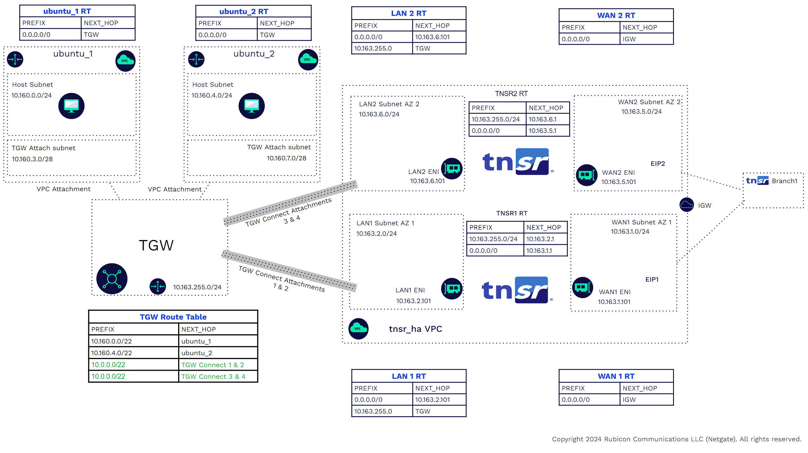
AS_PATH can be manipulated to prefer one TNSR VPN concentrator over another for all CIDRs or a subset of those CIDRS.
Deployment
Please visit Netgate’s GitHub page for Terraform Automation of TNSR topologies. Scripts are available for full POV/POC testing.
Deployment Steps. (This includes only the required configuration for IPSEC, GRE, BGP, Static Routing, and Interfaces). System settings (SNMP, IPFIX, Logging, NTP, etc..) will not be covered. Please visit our documentation page for more details.
1) Create a VPC with three subnets (Mgmt, WAN, LAN), each with its own route tables. For High Availability (HA), create another three subnets in a different Availability Zone (AZ).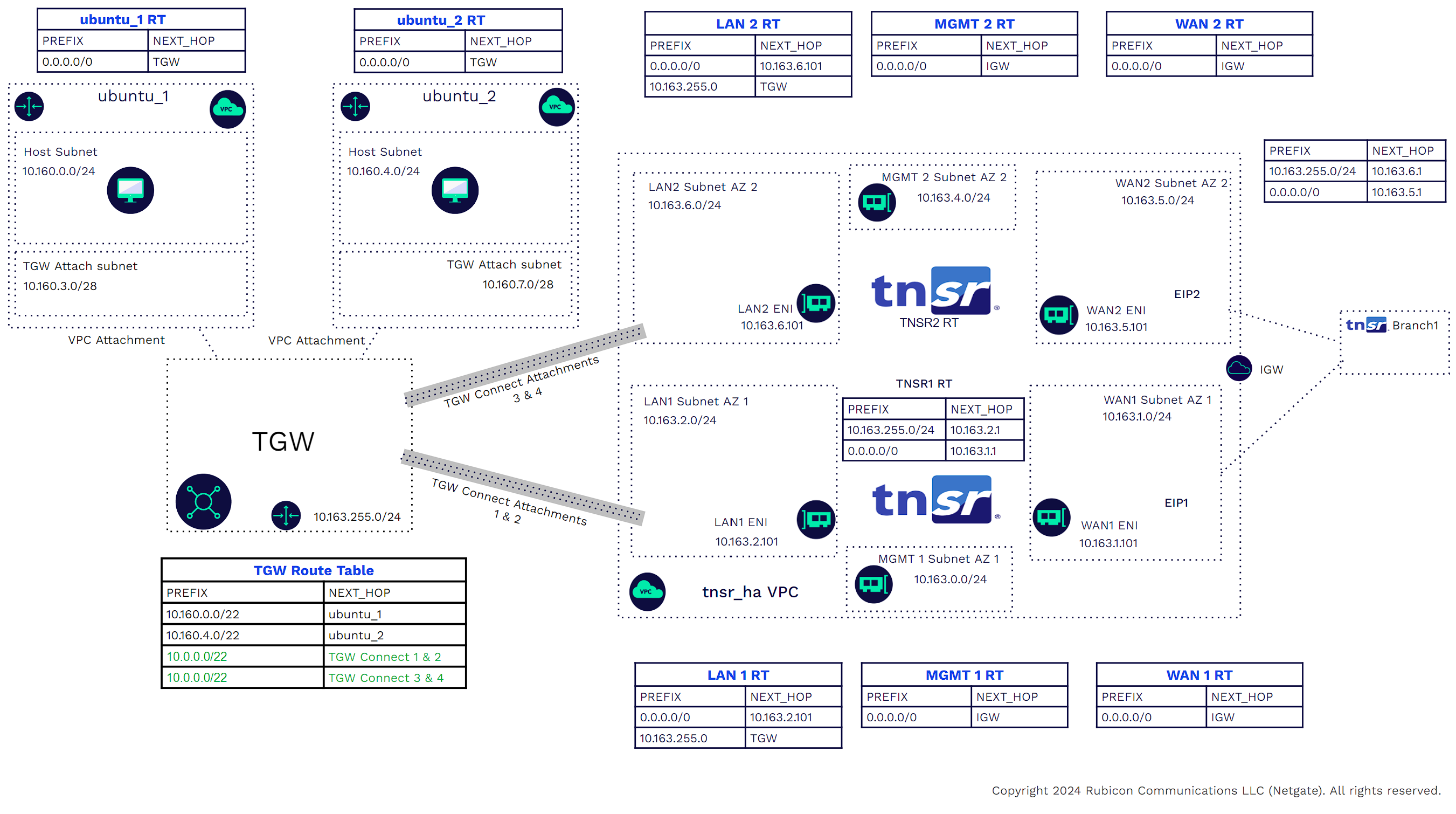
2) Instantiate TNSR appliances in the VPC
https://docs.netgate.com/tnsr/en/latest/platforms/aws/
Note:
Access is required to the TNSR management interfaces through an external connection or an internal mgmt VPC/Bastion Host. Be sure to configure routing, Network Security Groups, and ACLs appropriately. 3) Configure the TNSR routers. For a detailed script file please visit our Netgate Github tnsr-tgw-connect-ha repo.
3a) Data Plane interfaces
configure terminal
dataplane dpdk dev 0000:00:06.0 network name WAN
dataplane dpdk dev 0000:00:07.0 network name LAN
service dataplane restart
int WAN
desc WAN
ip add 10.163.1.101/24
enable
exit
int LAN
desc LAN
ip add 10.163.2.101/24
enable
exit
3b) IPSEC to Branch
tunnel ipip 1
source ipv4 address 10.163.1.101
destination ipv4 address 54.241.125.171
exit
ipsec tunnel 1
enable
crypto config-type ike
crypto ike
version 2
lifetime 28800
proposal 1
encryption aes128
integrity sha256
group modp2048
exit
identity local
type address
value 54.241.110.249
exit
identity remote
type address
value 54.241.125.171
exit
authentication local
round 1
psk mysupersecretkey
exit
exit
authentication remote
round 1
psk mysupersecretkey
exit
exit
child 1
lifetime 3600
proposal 1
encryption aes128
integrity sha256
group modp2048
exit
exit
exit
exit
interface ipip1
enable
ip address 172.31.101.2/30
mtu 1400
exit
wr
3c) IPV4 Default route to AWS WAN subnet route-table.
route table ipv4-VRF:0
route 0.0.0.0/0
next-hop 0 via 10.163.1.1
exit
exit
The AWS WAN subnet route-table will have a default route with a NEXT_HOP = the AWS VPC internet gateway. This route allows Internet connectivity.
3d) IPV4 route to the TGW with NEXT_HOP = AWS LAN Subnet Route-Table.
route table ipv4-VRF:0
route 10.163.255.0/24
next-hop 0 via 10.163.2.1
exit
exit
The AWS LAN subnet route-table will have a route to the TGW CIDR with a NEXT_HOP = the AWS TGW. This route allows us to form the GRE tunnels between the TNSR instance and TGW. Remember, we are using private IP Addresses for the GRE termination. These will form over the virtual link VPC attachment.
3e) Configure BGP facing the branches
route dynamic bgp
enable
server vrf default
as-number 65201
router-id 10.163.1.101
no ebgp-requires-policy
no network import-check
neighbor 172.31.101.1
remote-as 65301
enable
exit
exit
exit
Configure other BGP parameters between the branch and TNSR. These include passwords, timers, EBG Multihop, etc..
3f) Configure the GRE tunnel between the TNSR LAN interface and TGW GRE tunnel endpoints. AWS requires us to /29 internal tunnel CIDRS from the 169.254.0.0/16 CIDR.
conf terminal
gre intgre1
instance 1
source 10.163.2.101
dest 10.163.255.101
exit
int gre1
ip addr 169.254.100.1/29
enable
exit
gre intgre2
instance 2
source 10.163.2.101
dest 10.163.255.102
exit
int gre2
ip addr 169.254.100.9/29
enable
exit
3g) Configure BGP between the TNSR and TGW BGP endpoints. Two TGW BGP endpoints per GRE tunnel (four total). AWS timers are 10 and 30 for keepalive and hold time. ebgp-multihop with a max hop of at least two is needed.
https://docs.aws.amazon.com/vpc/latest/tgw/tgw-connect.html
route dynamic bgp
server vrf default
neighbor 169.254.100.2
remote-as 65101
ebgp-multihop max-hop 2
timers keep-alive 10 hold-time 30
timer
enable
exit
neighbor 169.254.100.3
remote-as 65101
ebgp-multihop max-hop 2
timers keep-alive 10 hold-time 30
enable
exit
neighbor 169.254.100.10
remote-as 65101
ebgp-multihop max-hop 2
timers keep-alive 10 hold-time 30
enable
exit
neighbor 169.254.100.11
remote-as 65101
ebgp-multihop max-hop 2
timers keep-alive 10 hold-time 30
enable
exit
wr
exit
4) Configure AWS
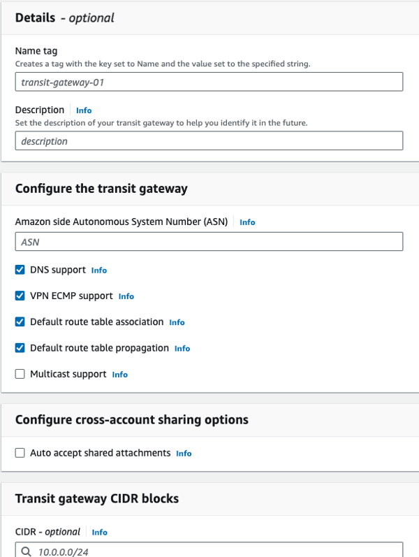
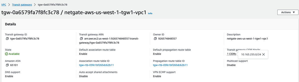
4a) Create the TGW with a CIDR
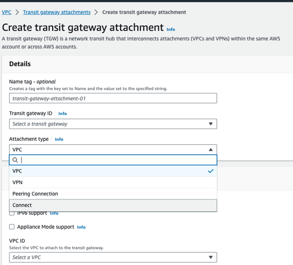
4b) Create the VPC attachments
VPC attachments for the workload VPCs and Connect attachments for the TNSR VPC are required.
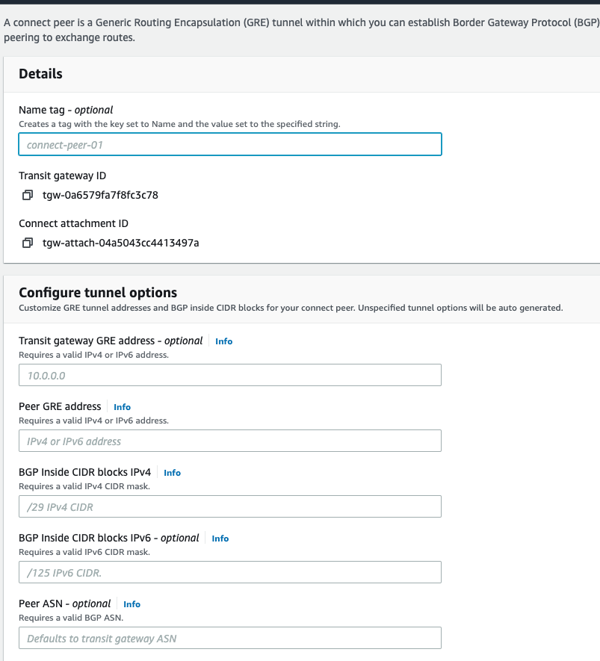
4c) Create connected pairs for the connect attachments. This brings up the GRE and BGP endpoints on the TGW Side. If IP addresses are not specifically assigned, AWS will allocate them.
4d) Add route to TGW CIDR to the AWS LAN subnet route-table with a NEXT_HOP = the AWS TGW. This route allows formation of the GRE tunnels between the TNSR instance and TGW. Private IP Addresses are used for the GRE termination. These will form over the virtual link VPC attachment.
5) Verification
5a) Verify BGP on TNSR. Neighbors should be visible and up.
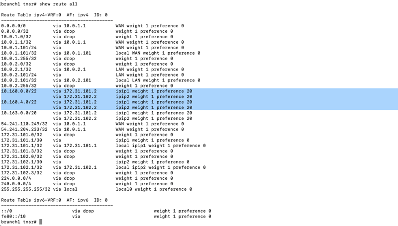
tnsrha1 tnsr(config)# show route dynamic bgp summary
IPv4 Unicast Summary (VRF default):
BGP router identifier 10.163.1.101, local AS number 65201 vrf-id 0
BGP table version 23
RIB entries 8, using 1536 bytes of memory
Peers 5, using 3623 KiB of memory
Total number of neighbors 5
tnsrha1 tnsr(config)#

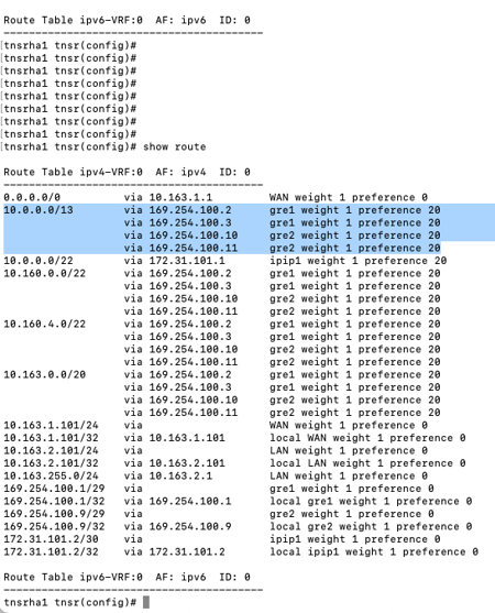
5b) Verify routes in TNSR
VPC CIDRs from the TGW should be visible.
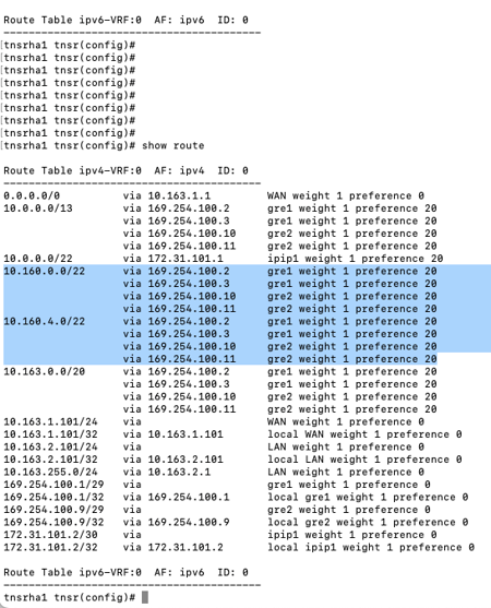
External Branch CIDRs from the TGW should be visible.
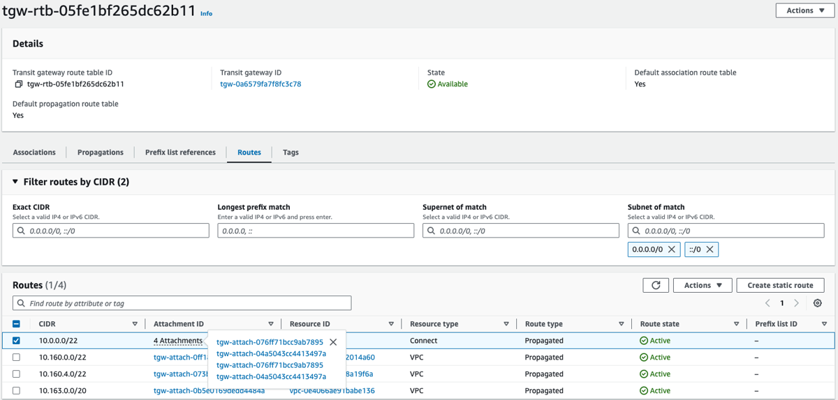
5c) Verify Routes on TGW
Four attachments for external CIDRs should be visible. There are two attachments for each TNSR instance.
5d) Verify routes at the branch
VPC workload CIDRs at your branch or DC should be visible.