Input and Output Ports
Rear Side
The rear side of the Netgate 4200 contains several items of interest for connecting to and managing the device.
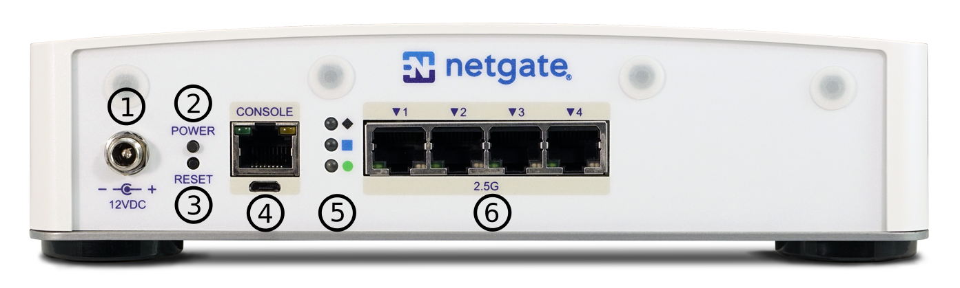
Rear view of the Netgate 4200 Firewall Appliance
The items below are marked with circled numbers on figure Rear view of the Netgate 4200 Firewall Appliance:
Item |
Description |
|---|---|
1 |
Power Connector |
2 |
ACPI Power Button (Protruding) - Graceful shutdown, hard power off (Hold 10s), power on |
3 |
Reset Button (Recessed) - Used when performing the Factory Reset Procedure. |
4 |
|
5 |
Rear Status LEDs |
6 |
- Power Connector (1)
The Power connector is 12VDC with threaded locking connector. Power consumption is approximately 13W when idle.
- Power Button (2)
The upper protruding Power Button behaves the same as a typical ACPI power button.
If the device is powered on and running, pressing the button immediately performs a graceful shutdown and the system enters a standby state.
If the system is in a powered off or standby state, pressing the power button immediately powers on the device and starts the boot process.
If the system is unresponsive, holding in the power button for 10 seconds will forcefully power off the device. Press the power button again to turn it back on.
- Reset Button (3)
The lower recessed Reset Button is used to perform the Factory Reset Procedure.
Pressing and immediately releasing the button has no effect, it does not perform a hardware reset.
See Factory Reset Procedure for details on how to use the button to perform a factory reset.
- Serial Console Port (4)
Clients can access the serial console using the USB Micro-B (5-pin) serial adapter port and a compatible USB cable or via the RJ45 “Cisco” style port with a separate cable and USB serial adapter or client hardware port.
Note
Only one type of console connection will work at a time and the RJ45 console connection has priority. If both ports are connected only the RJ45 console port will function.
Note
The serial console in the OS is a memory mapped serial port and not a traditional COM port. pfSense® Plus automatically detects and uses the correct console type for this device.
Note
The RJ45 Serial Console port is only for use with the Serial Console. It cannot be used for any other purpose.
- Status LEDs (5)
The rear status LEDs show the same output as the status LEDs on the front of the unit. See Status LEDs for information on interpreting the meaning of different LED states.
- Networking Ports (6)
This group of four ports are the network interfaces. They are explained in detail in the next section, Networking Ports.
Networking Ports
The section on the rear of the device numbered 6 in Rear view of the Netgate 4200 Firewall Appliance contains the network interfaces. These ports are labeled 1 through 4 on the device.
Label |
Assigned Name |
Device Name |
Type |
Speed |
|---|---|---|---|---|
1 |
PORT1WAN |
igc3 |
RJ-45 |
2.5 Gbps |
2 |
PORT2LAN |
igc2 |
RJ-45 |
2.5 Gbps |
3 |
PORT3 |
igc1 |
RJ-45 |
2.5 Gbps |
4 |
PORT4 |
igc0 |
RJ-45 |
2.5 Gbps |
Note
The igc(4) network interfaces on this device do not
support fixed speed operation. These interfaces emulate a speed/duplex choice
by limiting the values offered during autonegotiation to the speed/duplex
value selected in the GUI.
When connecting different devices to these interfaces the peer should typically be set to autonegotiate, not to a specific speed or duplex value. The exception to this is if the peer interface has the same limitation, in which case both peers should select the same negotiation speed.
Front Side
The front of the device has Status LEDs as well as an access panel for future expansion uses.
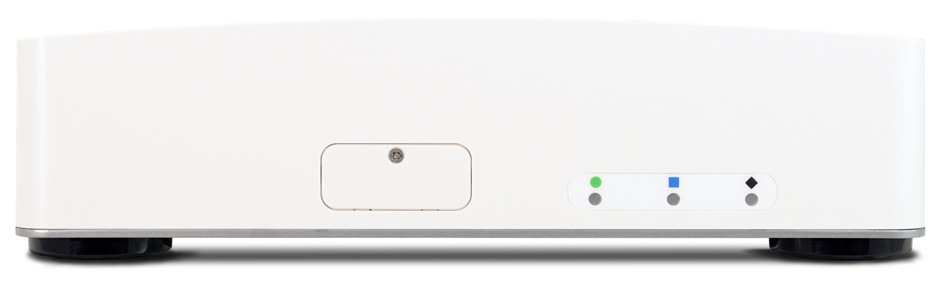
Front view of the Netgate 4200 Firewall Appliance
Right Side
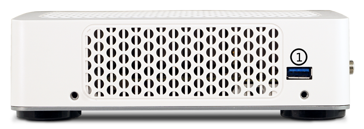
Right side view of the Netgate 4200 Firewall Appliance
The right side panel of the device (when facing the front) contains:
# |
Description |
Purpose |
|---|---|---|
1 |
USB 3.0 Port |
Connect USB devices |
USB Ports
USB ports on the device can be used for a variety of purposes.
The primary use for the USB ports is to install or reinstall the operating system on the device. Beyond that, there are numerous USB devices which can expand the base functionality of the hardware, including some supported by add-on packages. For example, UPS/Battery Backups, Cellular modems, GPS units, and storage devices. Though the operating system also supports wired and wireless network devices, these are not ideal and should be avoided.
Status LEDs
The Netgate 4200 has two sets of status LEDs: One on the front of the device and one on the rear. The status LEDs on the front are horizontal while the LEDs on the rear are arranged vertically. Though the placement is different, both sets are labeled consistently.
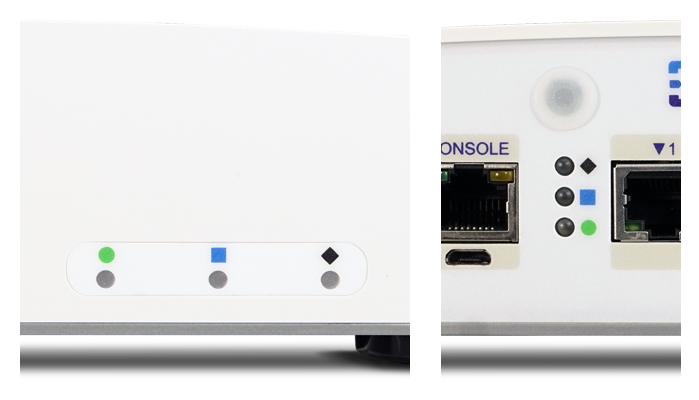
Status LEDs on the front (left) and rear (right) of the Netgate 4200 Firewall Appliance
LED Patterns
Description |
LED Pattern |
|---|---|
Standby |
Circle pulsing orange |
Boot in Process |
Diamond flashing blue |
Boot Completed/Ready |
Diamond solid blue |
Upgrade Available |
Square solid purple |
Upgrade in Progress |
All rapidly flash green |
Triggering Reset |
Circle, Square, then Diamond solid red (Factory Reset Procedure) |
Reset In Progress |
All rapidly flash red (Factory Reset Procedure) |