pfSense 2.4: Router-on-a-Stick
The following guide explains how to install pfSense® software version 2.4 on a single Ethernet port Minnowboard Turbot and configuring it as a router-on-a-stick.
Requirements:
USB stick with pfSense version 2.4 installer. Note, UEFI is supported starting with pfSense version 2.4 onward, earlier pfSense versions will not boot.
8 - 16 GB microSD card. This guide will cover installing pfSense on microSD, however using a SATA hard drive or mSATA (via a lure) will also work.
Layer 2 switch configured with two ports using VLAN’s 10 and 20. Third port configured as trunk.
USB to serial adapter (for console output). You can also use an HDMI cable instead of FTDI.
Note
Minnowboards have a HDMI output as well as console output via UART pins. For this guide we'll be using console output however it applies to HDMI / monitor output as well.
This guide assumes the switch is configured with the following layout:
VLAN 10 port - used for WAN, connected to upstream modem.
VLAN 20 port - used for LAN, connected to clients.
TRUNK port - connected to Minnowboard Turbot
Steps:
Navigate to the pfSense Download Page to download pfSense. Choose the 2.4.x version or later, AMD64 (64-bit), USB Memstick Installer, and Serial (if you are using the UART pins). Choose the mirror of your choice (generally the one closest to you).
Note
If you are using HDMI, select VGA instead of Serial.
Write the downloaded image to a USB memstick (thumbdrive).
See also
Visit Writing an OS Installation Image to Flash Media for instructions on creating a USB thumbdrive.
Connect USB serial adapter's GND, RXD, TXD pins to UART.
Warning
If using USB serial adapter with the power pin plugged in, do not connect the Minnowboard power supply, it will damage the board.
Plug in the USB thumbdrive with pfSense installer to USB 3.0 port on the Minnowboard.
Insert the microSD card into the microSD slot.
Connect Minnowboard ethernet to your previously configured switch port with VLAN 10 and VLAN 20 tags.
Connect WAN to your VLAN 10 tagged switch port and connect LAN client to VLAN 20 tagged switch port.
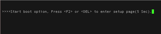
Power on the unit and press DEL to enter Minnowboard UEFI setup.
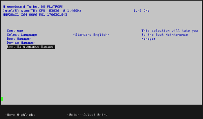
On UEFI setup select Boot Manager and press enter.
Select EFI USB Device and press enter to start pfSense boot.
Wait for pfSense to boot automatically.
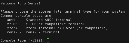
When prompted for appropriate terminal type select xterm.
Once pfSense setup starts, choose Accept on the Copyright and distribution notice.
Follow the default selections to install pfSense on the microSD.
On the Welcome screen, select Install to install pfSense.
On the Keymap Selection screen, choose Continue with the default keymap and press enter.
On the partitioning screen, keep the default Auto (UFS) Guided Disk Setup selection and press enter.
Wait for installation to complete and choose Reboot.
After pfSense is installed setup will complete and reboot. Once again press DEL to enter setup and go to Boot Maintenance Manager.
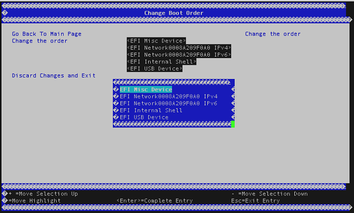
Select Change Boot Order.
Change the order and move EFI Misc Device to list top. Press enter to save and return to the previous screen.
Select Continue from the main EFI setup screen and wait for pfSense to boot. From now on, the microSD will boot by default.
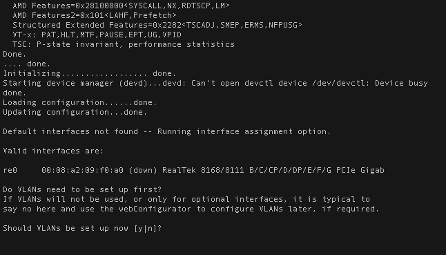
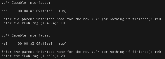
At first post-install boot we will configure VLAN’s. Confirm re0 is listed as a valid interface continue and confirm with Y to set up VLAN’s now.
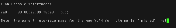
In order to assign interfaces we must first create two VLAN’s, VLAN 10 (WAN) and VLAN 20 (LAN). Enter re0 when prompted for a parent interface name.
Enter 10 as VLAN tag to add WAN interface.
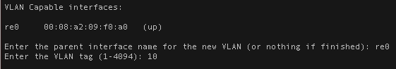
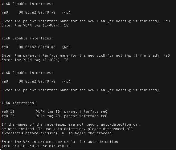
Enter 20 as VLAN tag to add LAN interface.
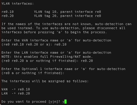
Once VLAN 10 and VLAN 20 are created assign WAN and LAN to previously created VLAN’s. Assign re0.10 to WAN and re0.20 to LAN.
Review the assigned interfaces, make sure it matches the screenshot and press Y to continue pfSense boot.
pfSense will complete bootup and if every step was followed correctly, your WAN should have an external IP.
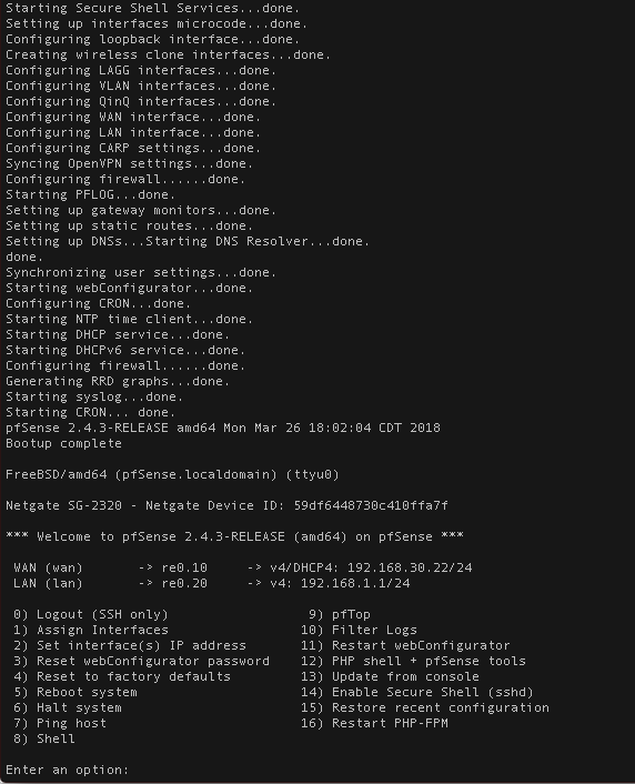
Verify interfaces are correctly assigned by opening a browser and navigating to the default 192.168.1.1 IP address.
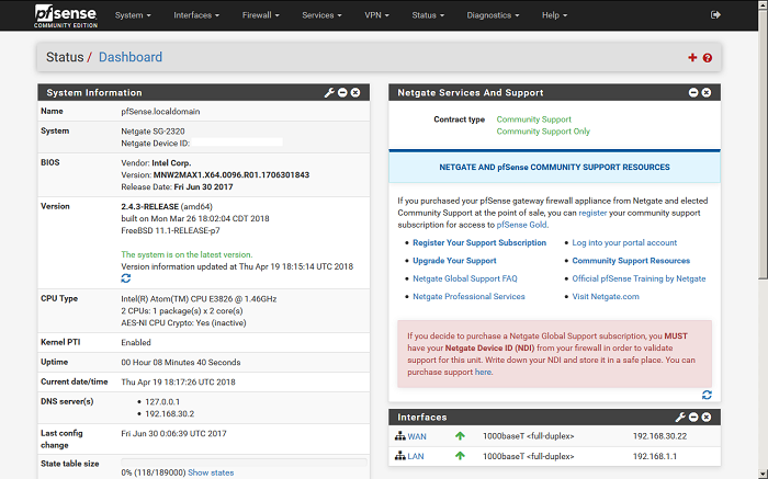
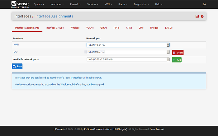
Under Interfaces > Interface Assignments confirm VLAN 10 on re0 is assigned as WAN and VLAN 20 on re0 is assigned as LAN.
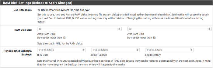
In order to limit microSD card wear, we recommend enabling RAM disks. Navigate to System > Advanced > Miscellaneous and select Use RAM Disks.