Input and Output Ports
Front Side
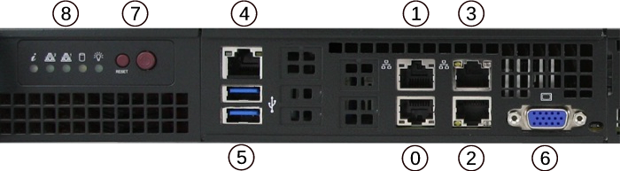
Front view of the Netgate 1541 Firewall Appliance
The numbered labels in this image refer to entries in Network Ports and Other Ports.
Network Ports
Default Ports
When no expansion card is installed, this is the default port configuration.
Port |
Interface Name |
Port Name |
Port Type |
Port Speed |
|---|---|---|---|---|
0 |
OPT1 |
igb0 |
RJ-45 |
1 Gbps |
1 |
OPT2 |
igb1 |
RJ-45 |
1 Gbps |
2 |
WAN |
ix0 |
RJ-45 |
10 Gbps |
3 |
LAN |
ix1 |
RJ-45 |
10 Gbps |
Note
Both the WAN and LAN ports of the Netgate® appliance support auto-MDIX and are capable of utilizing either straight-through or crossover Ethernet cables.
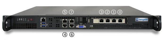
Optional Quad Port Expansion Cards
Default port configuration for 4-port expansion cards.
4-port 1GbE Supermicro AOC-SGP-i4
4-port 10GbE Intel X710BM2
Port |
Interface Name |
Port Name |
Port Type |
Port Speed |
||||
|---|---|---|---|---|---|---|---|---|
# |
SGP-i4 |
X710 |
SGP-i4 |
X710 |
SGP-i4 |
X710 |
SGP-i4 |
X710 |
0 |
OPT6 |
Unassigned |
igb0 |
ixl0 |
RJ-45 |
SFP+ |
1 Gbps |
10 Gbps |
1 |
OPT5 |
Unassigned |
igb1 |
ixl1 |
RJ-45 |
SFP+ |
1 Gbps |
10 Gbps |
2 |
OPT4 |
Unassigned |
igb2 |
ixl2 |
RJ-45 |
SFP+ |
1 Gbps |
10 Gbps |
3 |
OPT3 |
Unassigned |
igb3 |
ixl3 |
RJ-45 |
SFP+ |
1 Gbps |
10 Gbps |
4 |
WAN |
WAN |
igb4 |
igb0 |
RJ-45 |
RJ-45 |
1 Gbps |
1 Gbps |
5 |
LAN |
LAN |
igb5 |
igb1 |
RJ-45 |
RJ-45 |
1 Gbps |
1 Gbps |
6 |
OPT1 |
OPT1 |
ix0 |
ix0 |
RJ-45 |
RJ-45 |
10 Gbps |
10 Gbps |
7 |
OPT2 |
OPT2 |
ix1 |
ix1 |
RJ-45 |
RJ-45 |
10 Gbps |
10 Gbps |
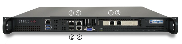
Optional Dual Port Expansion Cards
Default port configuraiton for 2-port expansion cards.
2-port 10GbE Chelsio T520-CR
2-port 10GbE Intel X710BM2
Port |
Interface Name |
Port Name |
Port Type |
Port Speed |
||
|---|---|---|---|---|---|---|
# |
T520 |
X710 |
T520 |
X710 |
T520/X710 |
T520/X710 |
0 |
WAN |
Unassigned |
cxl0 |
ixl0 |
SFP+ |
10 Gbps |
1 |
LAN |
Unassigned |
cxl1 |
ixl1 |
SFP+ |
10 Gbps |
2 |
OPT1 |
WAN |
igb0 |
igb0 |
RJ-45 |
1 Gbps |
3 |
OPT3 |
LAN |
igb1 |
igb1 |
RJ-45 |
1 Gbps |
4 |
OPT2 |
OPT1 |
ix0 |
ix0 |
RJ-45 |
10 Gbps |
5 |
OPT4 |
OPT2 |
ix1 |
ix1 |
RJ-45 |
10 Gbps |
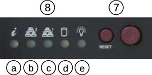
Status LEDs
LED |
State |
Description |
|---|---|---|
8a |
Continuously on and red
|
An overheat condition has occurred.
(This may be caused by cable congestion.)
|
Blinking red (1Hz)
|
Fan failure, check for an inoperative fan.
|
|
Blinking red (0.25Hz)
|
Power failure, check for a non-operational power supply.
|
|
Solid blue
|
Local UID has been activated. Use this function through
IPMI to locate the server in a rack mount environment.
|
|
Blinking blue
|
Remote UID is on. Use this function through IPMI to
identify the server from a remote location.
|
|
8b |
Flashing
|
Indicates network activity on igb1 (upper left port).
|
8c |
Flashing
|
Indicates network activity on igb0 (lower left port).
|
8d |
Flashing
|
Indicates IDE channel activity on the hard drive.
|
8e |
Illuminated
|
Indicates power is being supplied to the system power supply
units. This LED should normally be illuminated when the
system is operating.
|
Off
|
Indicates no power is being supplied to the system power
supply. System is powered off.
|
Other Ports
Port |
I/O Type |
|---|---|
4 |
IPMI |
5 |
2x USB 3.0 Ports |
6 |
|
7 |
Reset & Power buttons |
8 |
Status LEDs |
USB Ports
USB ports on the device can be used for a variety of purposes.
The primary use for the USB ports is to install or reinstall the operating system on the device. Beyond that, there are numerous USB devices which can expand the base functionality of the hardware, including some supported by add-on packages. For example, UPS/Battery Backups, Cellular modems, GPS units, and storage devices. Though the operating system also supports wired and wireless network devices, these are not ideal and should be avoided.